


 مدل XH-M222 4")


نقد و بررسی
- فرکانس خروجی:1 هرتز تا 150 کیلو هرتز
- دمای کاری: منفی 30 تا 70 سلیسیوس
- جریان خروجی: بین 8 تا 30 میلی آمپر
- باد ریت:9600 بیت بر ثانیه
- بیت توقف: 1 بیت
- دیتا بیت:8 بیت
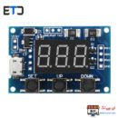
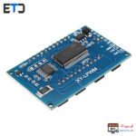
ماژول PWM ژنراتور دو کاناله به همراه سریال و نمایشگر
یک مولد تولیدکننده پالس با شکل های مختلف نظیر مربعی و تا فرکانس 150 کیلوهرتز بوده که می توان این فرکانس را توسط سون سگمنت مشاهده کرد.با استفاده از ماژول PWM دو کاناله با نمایشگر مدل HW-0515 کاربردی میتوان دو کاناله خروجی PWM داشت که کانال اول از 0 تا 999 هرتز و کانال دوم از 0 تا 150 کیلو هرتز میتواند خروجی داشته باشد.
ویدئو ماژول سیگنال ژنراتور PWM دو کاناله:
PWM یا همان Pulse-width modulation که به معنای مدولاسیون پهنای پالس می باشد نوعی مدولاسیون کنترل از طریق پهنای پالس خروجی می باشد که میتوان برای کنترل دور موتور،شدن روشنایی ،و مواردی از این دست مورد استفاده قرار گیرد.

ماژول PWM ژنراتور دو کاناله به همراه سریال و نمایشگر
“PWM ژنراتور دو کاناله: ساختار و کاربردها”
این ماژول الکترونیکی از نوع PWM ژنراتور دو کاناله با امکانات سریال و نمایشگر است که توانایی تولید سیگنالهای PWM با دقت و کنترل بالا را داراست. این ماژول به دلیل ویژگیهای منحصربهفردش به عنوان یک ابزار کلیدی در صنایع مختلف الکترونیکی شناخته شده است.
FAQ: “پرسشهای متداول”
1. آیا میتوان از این ماژول برای کنترل سرعت موتورها استفاده کرد؟
بله، این ماژول قابلیت کنترل دقیق سرعت موتورها را ارائه میدهد.
2. آیا نیاز به تنظیمات پیشرفته برای استفاده از این ماژول داریم؟
بله، برای بهرهمندی کامل از قابلیتهای ماژول، نیاز به آشنایی با تنظیمات پیشرفته دارید.
نتیجهگیری:
ماژول PWM ژنراتور دو کاناله با سریال و نمایشگر ابزار کاربردی و قدرتمندی است که برای کنترل دقیق و کاربردهای مختلف الکترونیکی بسیار مناسب است. استفاده از این ماژول با دانش متوسط به بالا در زمینه الکترونیک توصیه میشود تا بهرهوری بیشتری از قابلیتهای آن به دست آید.
ویژگی های ماژول PWM ژنراتور دو کاناله به همراه سریال و نمایشگر:
- ولتاژ ورودی:5 تا 30 ولت دی سی
- دارای ارتباط سریال
- دارای ورودی میکرو یو اس بی
- فرکانس خروجی:1 هرتز تا 150 کیلو هرتز
- دمای کاری: منفی 30 تا 70 سلیسیوس
- جریان خروجی: بین 8 تا 30 میلی آمپر
- باد ریت:9600 بیت بر ثانیه
- بیت توقف: 1 بیت
- دیتا بیت:8 بیت
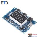
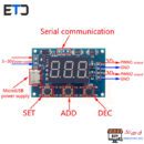
بر روی این ماژول سه دکمه وجود دارد که به وسیله ی راهنمای زیر میتوان فرکانس و پهنای باند را تنظیم کرد.
خرید مدل های مشابه ماژول PWM دو کاناله با نمایشگر مدل HW-0515:
- ماژول PWM ژنراتور XY-LPWM دو کاناله به همراه LCD
- ماژول فانکشن ژنراتور XR2206 با فرکانس 1Hz-1MHz
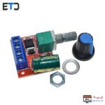
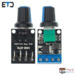
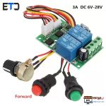
- ماژول کنترل سرعت موتور 2 آمپر PWM
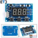
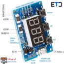
قطعات کلی بر روی ماژول PWM ژنراتور دو کاناله:

ماژول PWM ژنراتور دو کاناله به همراه سریال و نمایشگر
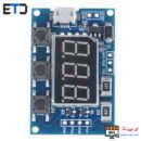
ترتیب دکمه های ماژول PWM ژنراتور دو کاناله به همراه سریال و نمایشگر:

ماژول PWM ژنراتور دو کاناله به همراه سریال و نمایشگر
HW-0515 2 Channel PWM Generator Module
Product Introduction:
1. Operating Voltage: 5-30V,support micro USB 5.0V power supply
2. Frequency Range: 1Hz~150KHz
3. Frequency Precision: 2%
4. Signal Load Capacity: output current is within 8–30mA
5. Output Range: default 5V V-pp (can be changed by external power)
6. Ambient Temperature: -30 Celsius ~70 Celsius
Application Fields:
1. As square wave generator to generate square wave for experiment development
2. Used to drive steeping motor driver’s square wave
3. Generate adjustable pulse for MCU using
4. Generate adjustable pulse for controlling relative circuit (PWM adjust light speed etc)
Serial Port Control:
1. Communication Standard:9600 bps
2. Data Bit:8
3. Stop Bit:1
4. Verify Bit: none
5. Flow Control: none
Setting PWM Frequency:
1.”S1FXXXT”: set PWM1 frequency as XXX HZ (001~999)
2.”S1FXX.XT”: set PWM1 frequency as XX.X KHZ (00.1~99.9)
3.”S1F:X.X.X.T”: set PWM1 frequency as XXX KHZ (0.0.1.~1.5.0.)
4.”S1″: PWM1
5.”S2″: PWM2
6.”F”: frequency
7.”D”: duty cycle
8.”T”: stop sign bit
Setting PWM Duty Cycle:
1.”S1DXXXT”: set PWM1 duty cycle as XXX;(001~100)
2.”S2DXXXT”: set PWM2 duty cycle as XXX;(001~100)
Setting successfully back: DOWN
Setting unsuccessfully back: FALL
Parameter Setting:
Module has 3-channel key: Set, Up, Down
1.By short press SET key, can shift display 4 parameter values (FR1 :PWM1 frequency; dU1: PWM1 duty cycle; FR2: PWM2 frequency; dU2: PWM2 duty cycle); before shifting, there will be corresponding parameter name flashing.
2. Directly press UP, DOWN key to modify current parameter value
3. 2-chhannel PWM are set 3 kinds frequency value, in frequency display interface, by long press SET to shift, 3 kinds frequency’s duty cycle are the same (XXX:1Hz~999Hz; XX.X:0.1Khz~99.9Khz;X.X.X.:1Khz~150Khz)
Package included:
1 x 2 Channel PWM Generator Module
0دیدگاه