


نقد و بررسی
- ولتاژ کاری: 3 تا 6 ولت دی سی
- تبدیل آنالوگ به دیجیتال تا 3.5 رقم
- فرکانس کاری:48 کیلو هرتز
- خروجی دیجیتال از 0 تا 1999
- دارای درایور داخلی برای 4 سون سگمنت
آی سی ولتمتر ICL7107 A/D
از این آی سی برای تبدیل آنالوگ به دیجیتال و از همه مهم تر برای ساخت ولتمتر دقیق استفاده می شود.این آی سی همانند اتمگا 16 و 32 دارای 40 پایه بوده که به بررسی آن ها می پردازیم.
این آی سی توانایی اندازه گیری ولتاژ تا بازه ی 60 ولت را دارا می باشد.
ویژگی های آی سی ولتمتر ICL7107 A/D:
- ولتاژ کاری: 3 تا 6 ولت دی سی
- تبدیل آنالوگ به دیجیتال تا 3.5 رقم
- فرکانس کاری:48 کیلو هرتز
- خروجی دیجیتال از 0 تا 1999
- دارای درایور داخلی برای 4 سون سگمنت
- تعداد پایه ها:40 عدد
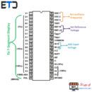
Pin Configuration:
| Pin Number | Pin Name | Description |
| 1 | Supply voltage (+) | Provides the operating voltage for the IC |
| 2,3,4,5,6,7 and 8 | 7-Segment 4th digit | These pins are connected to the 7-segment display for displaying the once digit of output value. |
| 9,10,11,12,13,14 and 25 | 7-segment 3rd digit | These pins are connected to 7-segment for displaying the tenth digit |
| 15,16,17,18,22,23 and 24 | 7-sement 2nd digit | These pins are connected to 7-segment for displaying the hundredth digit |
| 19 and 20 | 7-segment 1st digit | These pins are connected to 7-segment for displaying the thousandth digit |
| 21 | Ground | Connected to the round of the system |
| 26 | Supply voltage (-) | Provide the negative supply voltage |
| 27 | Signal integrate | Connected to a capacitor |
| 28 and 29 | Auto Zero and buff | Connected to capacitor and resistor network |
| 30 and 31 | Input High and Input Low | The analog voltage that has to be measured is connected here |
| 32 | Common | Connected to ground |
| 33 and 34 | Cref+ and Cref- | Capacitor is connected across these pins for neutralizing fluctuations in reference voltage |
| 35 and 36 | Reference High and Reference Low | Either can supply reference voltage or use internal reference voltage |
| 37 | Test pin | Not used during operation |
| 38, 39 and 40 | OSC1, OSC2, OSC3 | Use RC network top set oscillator frequency |
Features
3 ½ bit (0-1999) ADC module with 4-digit 7-segemnt display driver
Supply Voltage: Single Supply 0-6V
Dual Supply -15 to +15V
3 ½ ADC module
Analog input voltage is equal to supply voltage
Internal Oscillator is available
Typical operating frequency : 48kHz
Digital output value : 0 – 1999
Can drive four 7-segment display
Available in 40-pin PDIP, and MQFP
IC L7107 Equivalent
CS7107
Alternatives ICs
ADC0804, ADC modules
Where to use a ICL7107
The ICL7107 is an ADC module with a resolution of 3 ½ bit, meaning it can display digital value from 0-1999. The ADC used here is a dual slop ADC, so the applied voltage is compared with a reference voltage and then is approximated to find the applied voltage. The speciality of this IC is that it has an in-built 4-digit 7-segment display driver inside it. So to display the measured voltage we simply have to hook up 7-segment display to the output of the IC and everything is ready. IT eliminates the need for MCU/MPU or programming.
ماژول مبدل آنالوگ به دیجیتال 24 بیتی
The IC can measure voltages of maximum from -15V to +15V which is equal to the supply voltage.
The digital output can vary from 0-1999 where each digit is displayed on a single 7-segment display. So if you are trying to measure voltage and display them on a 7-segment display without the use of MCU or programming then this IC might be the right choice for you.
How to use ICL7107
Using ICL7107 is pretty straight forward, we just have to provide the reference voltage and set the internal clock for the ADC conversion to take place and we are all set. A basic sample circuit to measure voltage upto 200mV is shown below

The IC has an internal clock which can be set using the pins 38, 39 and 40 by using a Resistor capacitor network. The formulae to calculate the set oscillator frequency is shown below; typically the value is set to 48 kHz
FOSC = 0.45/RC
Once the clock is set we have to provide the reference voltage for the ADC conversion to take place. The value of the measured analog voltage will then be displayed on the 7-segment display the increment of count can be calculated using the following formulae

The accuracy and the range of the measured voltage can be measured by using external circuits involving potential divider or op-amps but as always there is a trade off between the accuracy and range. You can refer the datasheet at the end of this page to know more technical details.
Applications
Digital Voltmeter
Digital Ammeter
Instrument panel display
Non-programmable applications
ابعاد کلی آی سی ولتمتر ICL7107 A/D:


0دیدگاه