
جی دی تیGDT چیست؟
جی دی تیGDT چیست؟
شاید برای خیلی از دوستان سوال باشد که این المان چه نوع قطعه ای می باشد و چه کاربردی برای ما در صنعت الکترونیک و کامپیوتر دارد.
شاید شما تا به حال اصلا این قطعات را ندیده باشید یا اگر دیده باشید متوجه کارکرد آن نشده باشید و یا اصلا نفهمیده باشید این قطعه چه چیزی می باشد؟ در ابتدای امر این موضوع برای خود من نامفهموم و نامشخص بود.
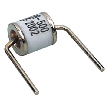
یادم میاد یه بار خواستم مودم وای فای خودم را که خراب شده بود تعمیر کنم بعد از کلی کلنجار رفتن با باز کردن درب مودم تونستم اون را باز کنم،شروع به بررسی قطعات کردم در ورودی مودم یه قطعه خیلی به چشمم خورد به طوری که اصلا قبلا چنین قطعه ای ندیده بودم ، شروع به بررسی قطعه کردم اسم روی قطعه و زیر برد رو خوندم بازم چیزی متوجه نشدم خلاصه بعد از کلی گشتن در سایت های ایرانی و خارجی فهمیدم چیه اون قطعه چیزی نبود جز یک GDT یا به فارسی لوله ی تخلیه گاز.
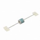
تصویر بالا یک جی دی تی GDT می باشد.این قطعه هنگام فعال شدن مانند مهتابی روشن می شود که در ابتدا یک پدیده جالب برای بنده بود.
بریم سر اصل مطلب،به توضیح جی دی تی GDT می پردازیم.
جی دی تی GDT یا به انگلیسی Gas Discharge Tube یک المان محافظت کننده در مدار بوده که وظیفه اصلی آن همانطور که گفته شد حفاظت از مدار در مقابل ولتاژ های ناخواسته می باشد.نحوه ساختار جی دی تی GDT همان طور که از نام آن پیداست از گاز می باشد.دو الکترود در دو سمت این قطعه قرار دارد و وسط آن را با یک نوع گا خاص پر می کنند این گاز می توان از گاز های نوع زیر باشد:
- Hydrogen gases یا گاز هیدروژن
- Deuterium gases یا گاز دئوتریوم
- Noble gases یا گاز نوبل
- (Elemental vapors (metals and nonmetals بخار خالص(بخار فلزات یا غیر فلزات)
- سایر گاز های نجیب(مانند:هلیوم ، نئون یا غیره)
نحوه عملکرد GDT:
در ابتدا باید بدانید که جی دی تی GDT در اکثر موارد به صورت موازی در مدار بسته می شود؛هنگامی که ولتاژ از حد مورد نظر ما بالاتر رود گاز درون جی دی تی یونیزه شده و بر افروخته شدن می شود و انرژی الکتریک اضافی دفع می شود بدین ترتیب از آسیب رساندن به مدار جلوگیری می کند.
تا زمانی که ولتاژ دو سر آن به ولتاژ کِلمپ Clamping Voltage آن نرسد غیر هادی باقی می ماند و جریانی از خود عبور نمی دهد.GDT ها دارای دو نوع ولتاژ متفاوت می باشند که هنگام خرید باید به آن ها توجه کرد یکی ولتاژ ای سی و دیگری دی سی می باشد.در واقع هر GDT دارای دو نوع ولتاژ قابل حفاظت یکی DC و دیگری AC می باشد.
دو مقاله پایین که به صورت انگلیسی بوده آموزش کاملی در مورد نحوه عملکرد و ساختار این قطعه مرموز در اختیار شما قرار می دهد.سعی می شود تا جای ممکن دو مقاله به صورت ترجمه در اختیار شما قرار گیرد.
Today’s microprocessor based electronic equipment are increasingly more vulnerable to lightning induced voltage surges and electrical switching transients because they have become more sensitive, and complex to protect due to their high chip density, binary logic functions and connection across different networks.A Gas Discharge Tube or GDT can be used as a standalone component or combined with other components to make a multistage protection circuit – the gas tube acts as the high energy handling component.
امروزه میکروپروسسور ها که پایه ی تجهیزات الکترونیک هستند به طور فزاینده ای در مقابل رعد برق و سایر عوامل خطر زا مانند ولتاژ های ناخواسته و زیاد و ولتاژ های بیش از اندازه ی دستگاه های سویچینگ برقی آسیب پذیر شده اند.
دلیل این امر نیز این است که این دستگاه ها حساس تر شده و حفاظت از آنها از لحاظ تعداد چیپ ها موجود در بر روی برد ، عملکرد باینری منطقی و اتصال به شبکه های مختلف پیچیده تر شده است.GDT یا به طور کامل Gas Discharge Tube میتونه به تنهای یا با سایر قطعات به عنوان لایه ی محافظتی چند گانه از مدار استفاده بشه.GDT به عنوان قطعه ای که کنترل میکنه انرژی بالایی رو عمل میکنه.
GDT’s are typically deployed in the protection of communication and data line DC voltage applications because of its very low capacitance. However, they provide very attractive benefits on the AC power line including no leakage current, high energy handling and better end of life characteristics.
GDT ها به طور خاص گسترش یافته اند برای حفاظت از خطوط ارتباطی و داده ای ولتاژ دی سی زیرا دارای ظرفیت خازنی پایینی می باشند.با این وجود آن ها سود های جذاب زیادی در خطوط قدرت ولتاژ ای سی از جمله عدم نشتی جریان ،قدرت کنترل انرژی زیاد و بهتر مشخصه طول عمر را فراهم آورده اند.
GAS DISCHARGE TUBE TECHNOLOGY
The gas discharge tube may be regarded as a sort of very fast switch having conductance properties that change very rapidly, when breakdown occurs, from open-circuit to quasi-short circuit (arc voltage about 20V). There are accordingly four operating domains in the behavior of a gas discharge tube:
Non-operating domain: Characterized by practically infinite insulation resistance.
Glow domain: At the breakdown, the conductance increases suddenly. If the current is drained off by the gas discharge tube is less than about 0.5A (rough value that differs from component to component) , the glow voltage across the terminals will be in the 80-100V range.
Arc regime: As the current increases, the gas discharge tube shifts from glow voltage to the arc voltage (20V). It is this domain that the gas discharge tube is most effective because the current discharge can reach several thousand amperes without the arc voltage across the terminals increasing.
Extinction: At a bias voltage roughly equal to the glow voltage, the gas discharge tube covers to its initial insulating properties.
End of Life
The gas discharge tubes are designed to withstand many impulses without destruction or loss of the initial characteristics (typical impulse tests are 10 times x 5kA impulses for each polarity).
On the other hand, a sustained very high current, i.e. 10A rms for 15 seconds, with simulate the dropping out of the AC power line onto a telecommunication line and will take the GDT immediately out of service.
If a fail-safe end of life is desired, i.e. short circuit that will report a fault to the end user when the line fault is detected, the gas discharge tube with the fail-safe feature (external short-circuit) should be selected.Selecting a Gas Discharge Tube
The information required to properly select a surge protector for your application is the following:
- طلاعاتی که شما نیاز دارید تا GDT را برای کارکرد خود انتخاب کنید:
- (DC sparkover voltage (Volts ولتاژ جرقه دی سی
- (Impulse sparkover voltage (Volts ولتاژ بر انگیختن
- (Discharge current capacity (kA ظرفیت تخلیه جریان
- (Insulation resistance (Gohms عایق مقاومتی
- (Capacitance (pF ظرفیت خازنی
- (Mounting (Surface Mount, Standard Leads, Custom Leads, Holder طریقه نصب
- (Packaging (Tape & Reel, Ammo pack بسته بندی
Range of DC sparkover voltage available:
محدوده ولتاژ جرقه موجود :
- Minimum 75V حداقل 75 ولت
- Average 230V میانگین 230 ولت
- High Voltage 500V حداکثر 500 ولت
- Very High Voltage 1000 to 3000V نهایت 1000 تا 3000 ولت
*Tolerance on the breakdown voltage is generally +/-20%
باید توجه داشت که این مقدار ها دارای تلرانس 20 درصد می باشند.
Insulation Resistance and Capacitance
These characteristics make the gas discharge tube practically invisible during normal operating conditions. The insulation resistance is very high (>10 Gohm) while the capacitance is very low (<1 pF).
عایق مقاومتی و خازنی:
این مشخصه باعث میشه GDT عملا در شرایط عادی بدون استفاده شود.عایق مقاومتی زمانی که عایق خازنی بسیار پایین هست(در حد کمتر از یک پیکو فاراد) درای مقداری بالایی(بیش از 10 گیگا اهم) شود.
در واقع به صورت ساده این معنا را می دهد:تا زمانی که ولتاژ به بیش از اندازه ی مورد نظر ما نرسد GDT دارای یک مقدار مقاومت بسیار بالا می باشد که اجازه ی دفع ولتاژ را نمی دهد.
STANDARDS
Test Standards and installation recommendations for communication line surge protectors must comply with the following standards:
UL497B : Protectors for Data Communications and Fire-Alarm Circuits.
استاندارد ها:
تست استاندارد و نصب توصیه شده برای حفاظت از خطوط ارتباطی باید کاملا بر اساس استاندارد زیر باشد:
UL497B یک استاندارد برای حفاظت از مدارات ارتباطی و مخابراتی و مدارات هشدار آتش می باشد.
INSTALLATION
To be effective, the surge protector must be installed in accordance with the following principles.
The ground point of the surge protector and of the protected equipment must be bonded.
The protection is installed at the service entrance of the installation to divert impulse current as soon as possible.
The surge protector must be installed in close proximity, less than 90 feet or 30 meters) to protected equipment. If this rule cannot be followed, secondary surge protectors must be installed near to the equipment
The grounding conductor (between the earth output of the protector and the installation bonding circuit) must be as short as possible (less than 1.5 feet or 0.50 meters) and have a cross sectional area of at least 2.5 mm squared.
The earth resistance must adhere to the local electrical code. No special earthing is necessary.
Protected and unprotected cables must be kept well apart to limit coupling.
MAINTENANCE
CITEL gas discharge tubes require no maintenance or replacement under normal conditions. They are designed to withstand repeated, heavy duty surge currents without damage.
Nevertheless, it is prudent to plan for the worst case scenario and, for this reason; CITEL has designed for the replacement of protection components where practical.
The status of your data line surge protector can be tested with CITEL’s model SPT1003. This unit is designed to test for the DC sparkover voltage, clamping voltages and line continuity (optional) of the surge protector. The SPT1003 is a compact, push button unit with a digital display. The voltage range of the tester is 0 to 999 volts. It can test individual components such GDT’s, diodes, MOVs or stand alone devices designed for AC or DC applications.
SPECIAL CONDITIONS: LIGHTNING PROTECTION SYSTEMS
If the structure to be protected is equipped with a LPS (Lightning Protection System), the surge protectors for telecom , data lines or AC power lines that are installed at the buildings service entrance need to be tested to a direct lightning impulse 10/350us wave form with a minimum surge current of 2.5kA (D1 category test IEC-61643-21).
شرایط خاص: سیستم حفاظت در برابر آذرخش(در اینجا منظور از هر چیزی که دارای ولتاژ بیش از اندازه باشد)
در صورتی که ساختار مورد نظر ما باید حفاظت خاصی در برابر آذرخش داشته باشد باید مجهز به یک LPS یا همان سیستم حفاظت از آذرخش ، حفاظت در برابر ولتاژ ناخواسته برای خطوط مخابراتی یا دیتا یا خطوط انتقال ولتاژ AC نیاز داره تا تست بشه توسط یک ولتاژ قوی تکان دهنده در حد فاصل 10 تا 350 میکرو ثانیه با حداقل جریان 2.5 کیلو آمپر.
Gas Discharge Tubes (GDT) – Introduction
GDT’s are special type of gas filled tubes used for wide range of electronic/electrical circuits for providing protection against lightning and other power surges. These tubes basically has two electrodes that are kept inside a gas filled closed envelope. In case of electronic applications, the container is mostly ceramic in nature. For high grade electrical applications military tubes are used. The electrical characteristics of this tubes depends on the pressure and composition of gas, and the distance between the two electrodes contained inside. The most commonly used gases in GDT’s are given below.
1) Hydrogen gases
2) Deuterium gases
3) Noble gases
4) Elemental vapors (metals and nonmetals)
5) Other gases
6) Insulating gases

مدار بالا یک نمونه نسبتا کامل برای حفاظت از مدار در برابر ولتاژ های ناخواسته می باشد.
The basic surge suppression circuit shown below consists of a VDR** (Voltage Dependent Resistor) and gas surge suppressor (GDT) connected in series. The protection circuit is connected between live and mains lead. Normally no current flows through GDT and VDR1. When the voltage between the terminals is higher than the sum of voltage ratings of GDT and VDR1 (here both GDT UZ470B and VDR S20K250 has 250v 16A rating), current starts to flow through those components.
If more the voltage rises then more current starts to flow through GDT and VDR1.When the current is normal, the circuit is reset and resumes it’s functioning. Thus the current cannot be raised much over that predetermined value.
When the voltage again goes back to normal values G1 and VDR1, the conducting stops and the circuit remains normal.
If the flowing current is more than the specified value of main self-resettable fuse, the fuse will break and the circuit will be protected. After the current is normal, the fuses resets and continue its functioning (protection against short circuit and overload).
The circuit is designed to protect sensitive electronic devices against over voltage transients in normal mains voltage and overload/ short circuit. Two neon pilot lamps are also provided with the circuit diagram to show the status of input and load supply.
اساس سرج ارستر یا بازدارنده ولتاژ یا به انگلیسی Surge Arrester or Surge protector که در مدار بالا نمایش داده شده را دو قطعه به خصوص با نام های VDR و GDT تشکیل می دهند که به صورت سری با هم وصل می شوند.
مدار محافظ بین ورودی اصلی برق و مدار اصلی بسته می شود.در حالت عادی هیچ ولتاژی از GDT و VDR عبور نمی کند.اما وقتی ولتاژ بین دو سر GDT و VDR از حد انتخاب شده بیشتر شود(مثلا در اینجا هر دو قطعه دارای ولتاژ 250 ولت و جریان 16 آمپر هستند)جریان از این دو قطعه شروع به عبور کردن می کند،سپس هر چه ولتاژ از حد عادی بیشتر شود جریان عبوری از این دو قطعه نیز بیشتر می شود.
زمانی که ولتاژ عادی هست این دو قطعه غیر فعال می شوند و مدار به کارکرد عادی خود ادامه می دهد.بدین ترتیب جریان از مقدار انتخاب شده هیچ گاه فراتر نخواهد رفت.وقتی که دوباره ولتاژ به حد عادی خود برگشت؛این دوقطعه دوباره اتصال خود را قطع می کنند و به حالت عادی خود بر می گردند.
در صورتی که جریان از حد عادی خود بیشتر شود فیوز قطع کننده ریست پذیر قطع شده و از آسیب رساندن به مدار جلوگیری می کند.سپس وقتی که جریان به حد عادی خود بازگشت دوباره فیوز به طور خودکار وصل شده و سپس به کار خود ادامه می دهد(در واقع هنگام استفاده از فیوز برگشت پذیر این امکان را به مدار می دهیم که دوباره و بدون نیاز به نیروی انسانی به کارکرد خود ادامه دهد مثلا در جایی دور افتاده که دسترسی به انسان و نیروی متخصص وجود ندارد).
این مدار طراحی شده تا از مدارات حساس در مقابل سر ریز ولتاژ و اتصال کوتاه و سر ریز جریان جلوگیری کند.دو لامپ نئون نیز برای نشان دادن وضعیت قرار داده شده اند.

سلام عالی بود
بسیارتشکر